Step 1. Initiate Load Balancer creation
Go to your project, navigate to the “Load Balancers” in the “Networking” section and click Create Load Balancer.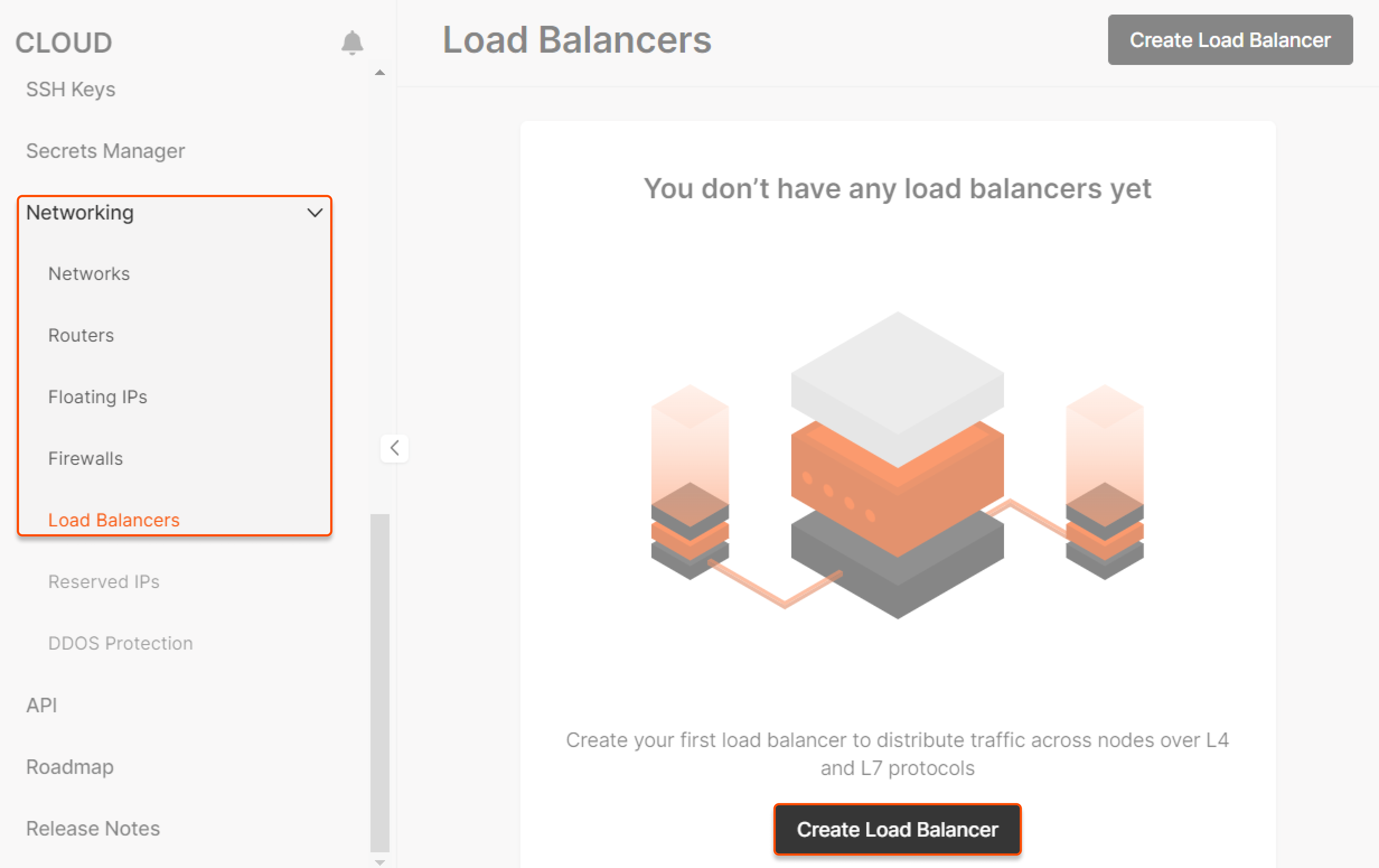
Step 2. Set the region
Select a region for balancing.WarningYou can balance traffic only within a single data center.
Step 3. Set computing configuration
Select a suitable computing configuration for your Load Balancer: GiB and vCPU. We create all Load Balancers in high availability mode with active-standby instances. Upon failure of the active instance, the standby one will seamlessly take over the load-balancing functions.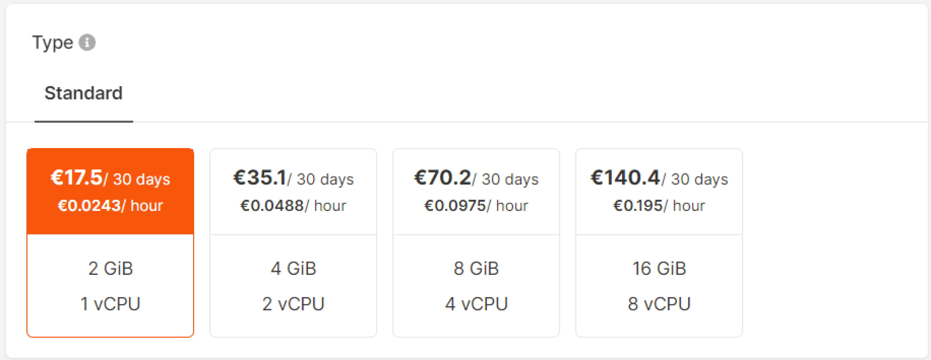
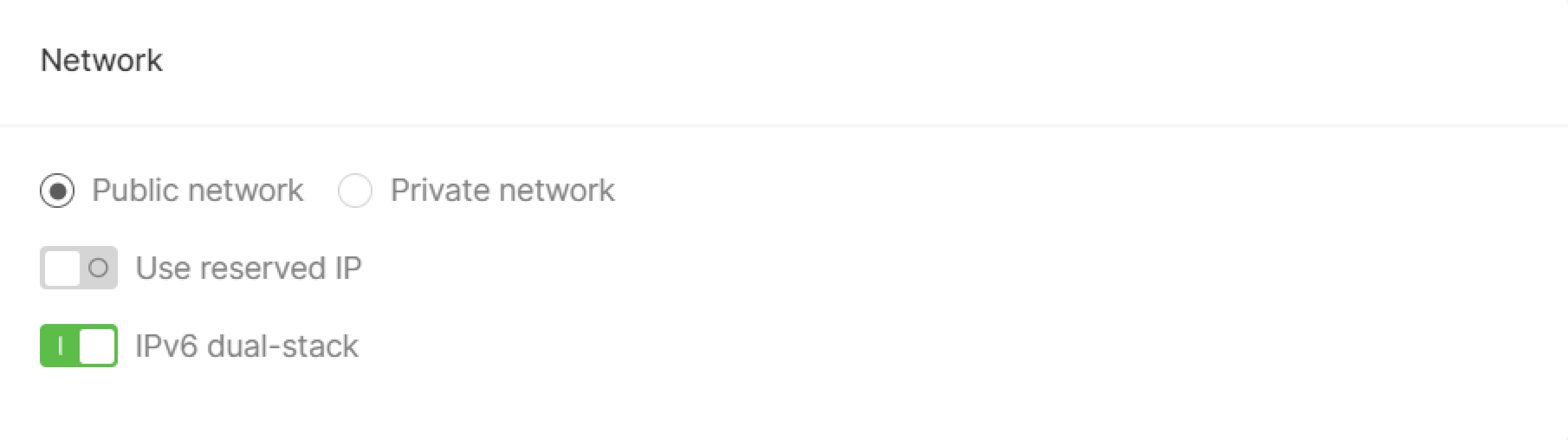
Step 4. Configure network
Select a network, public or private, and enable additional features:- Reserved IP and IPv6 dual-stack for the public network.
- Floating IP, reserved IP and IPv6 dual-stack for the private network.
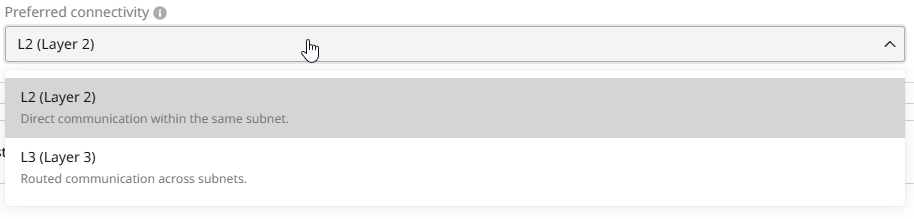
Step 5. Configure preferred connectivity
You can choose between L2 (Layer 2) and L3 (Layer 3) connectivity. This setting determines the preferred connectivity method the Load Balancer uses to connect to backend pool members. If the preferred connectivity is not feasible, traffic will automatically route via the alternative method: L2 (preferred) → (if not possible) L3 → (if not possible) Validation Error L3 (preferred) → (if not possible) L2 → (if not possible) Validation Error The Load Balancer determines available routes only by evaluating subnet host routes. Due to current system limitations, it does not take routerhost_routes into account.
Layer 2
L2 connectivity offers better performance because traffic flows directly between the Load Balancer and pool members without passing through a router. This reduces network hops and minimizes latency. However, this approach requires more IP addresses. In networks with many/24 subnets, each Load Balancer must create ports in every subnet where its members are located. This can lead to high IP utilization and reduced efficiency in large-scale deployments.
Layer 3
L3 connectivity routes traffic through a router or gateway, introducing additional network hops that may slightly impact performance. It also optimizes IP address utilization by reducing the number of required IPs per Load Balancer. Instead of allocating a separate IP in every subnet, the Load Balancer communicates with pool members across subnets using routing mechanisms. This approach improves scalability and efficiency, especially in environments with multiple subnets.TipFor most cases, such as a single subnet setup, use L2 connectivity for optimal performance. If your deployment involves multiple subnets or complex networking requirements, contact support to determine the best configuration.
Step 6. Configure listeners
Add listeners that will check for connection requests using the protocol and port that you specify. You can add multiple listeners to a Load Balancer. To configure a listener: 1. In the Listeners section, click Add listener.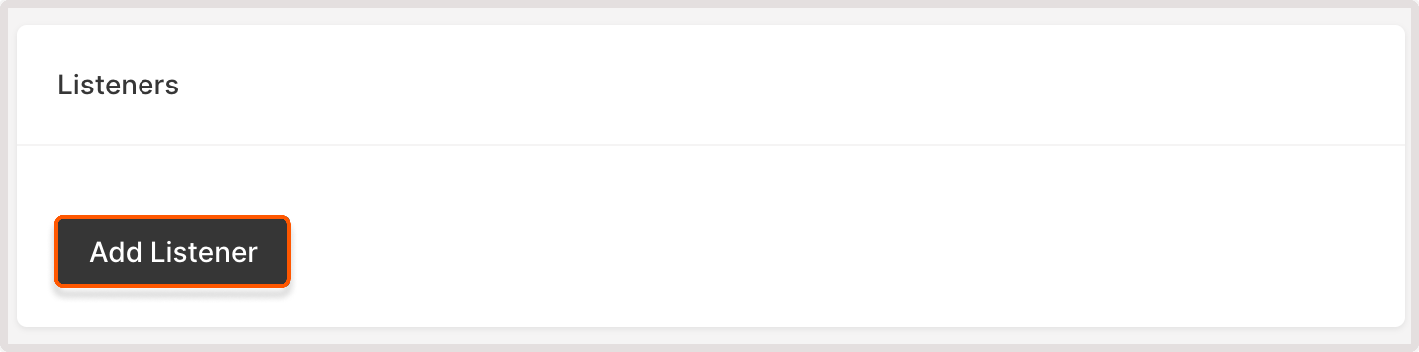
- VIPs with both IPv4 and IPv6 support CIDRs of both versions.
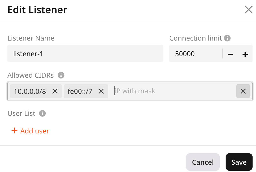
- VIPs with only IPv4 allow only IPv4 CIDRs
- VIPs with only IPv6 allow only IPv6 CIDRs
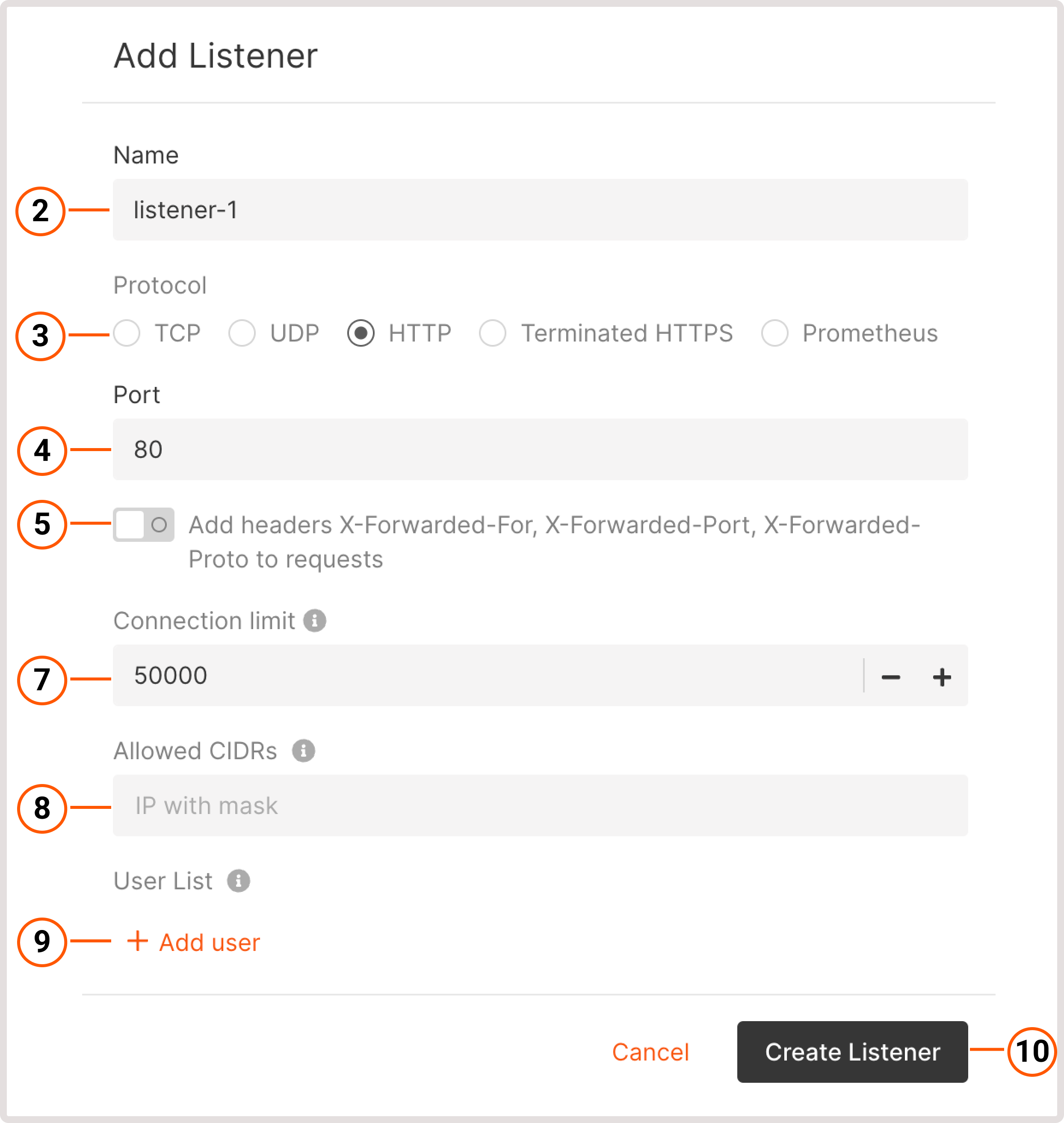
- Enter username : specify a username.
- Password : specify a password or choose the Encrypted password option to store password as a hash. Check out create an encrypted password for instructions.
InfoA password must contain at least one lowercase character, one uppercase character, at least one number, and a special character. The maximum password length is 128 symbols.
Pool
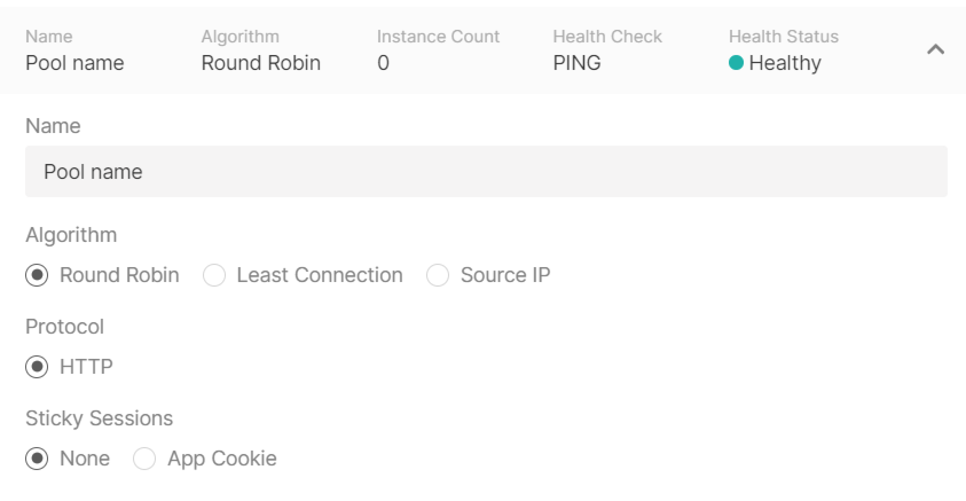
Configure a pool—a list of VMs to which the listener will redirect incoming traffic. Click Add new pool in the “Listeners” block to start configuring.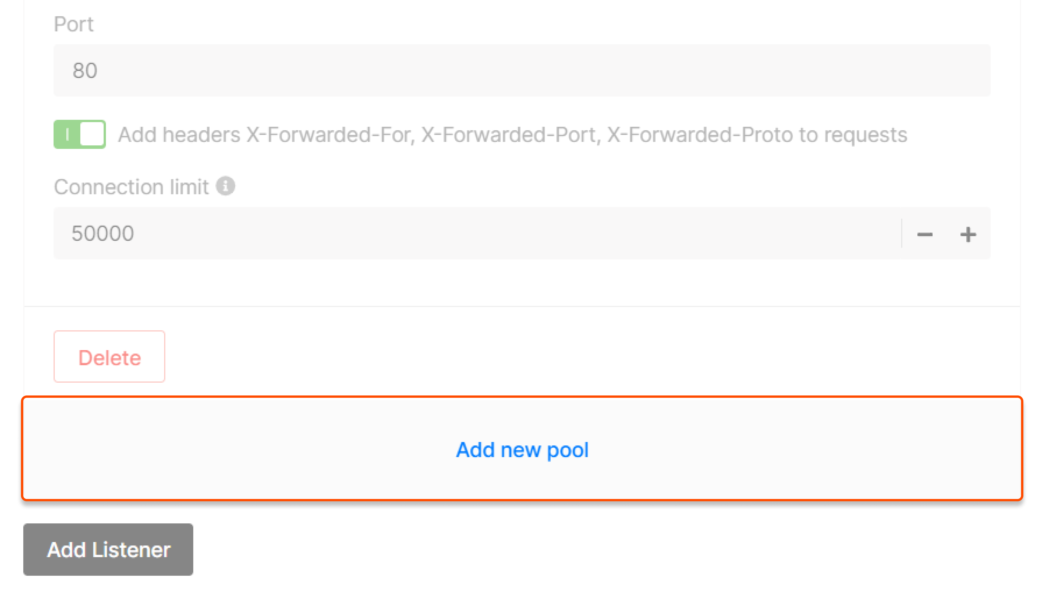
- Round robin —requests are distributed across servers within a cluster one by one: the first request is sent to the first server, the second request is sent to the second server, and so on in a circle.
- Least Connection —new requests are sent to a server with the fewest active connections.
- Source IP —a client’s IP address is used to determine which server receives the request.
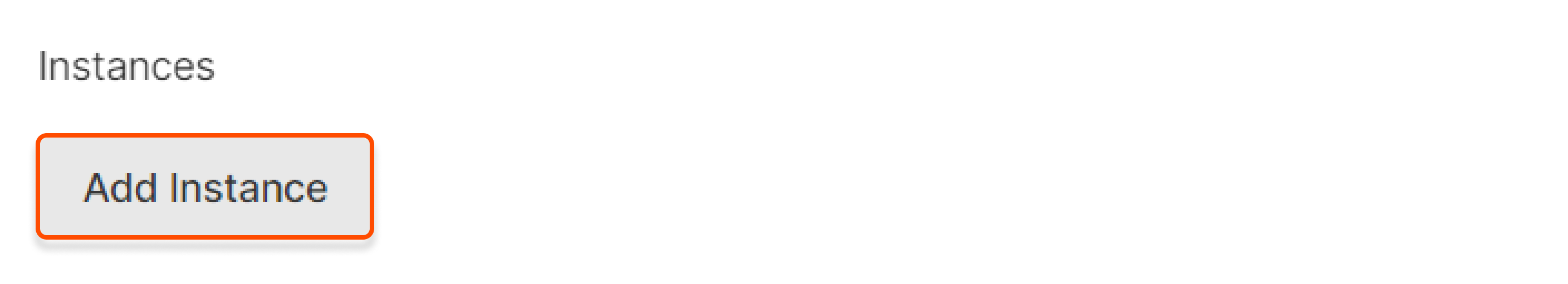
Virtual Machine
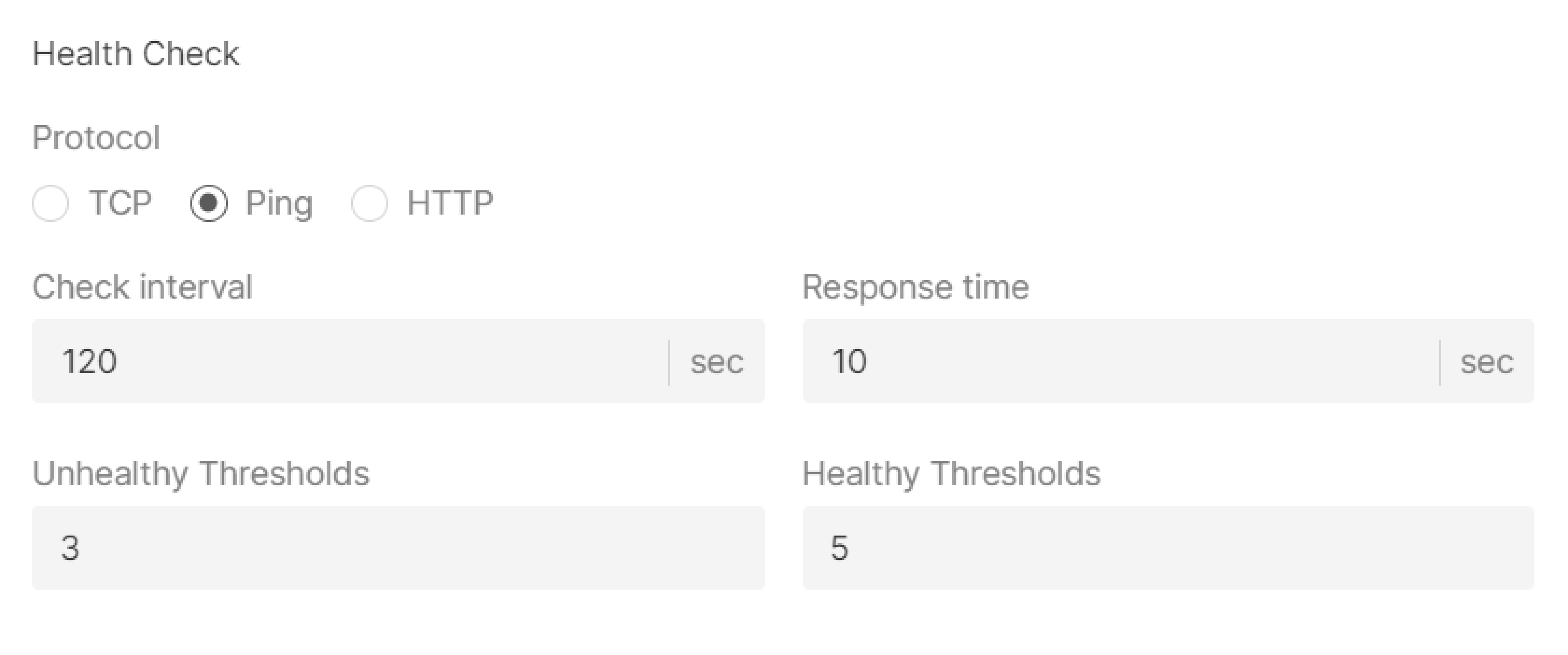
Health check
Timeouts
Specify client data, member connect and member data timeouts in msec.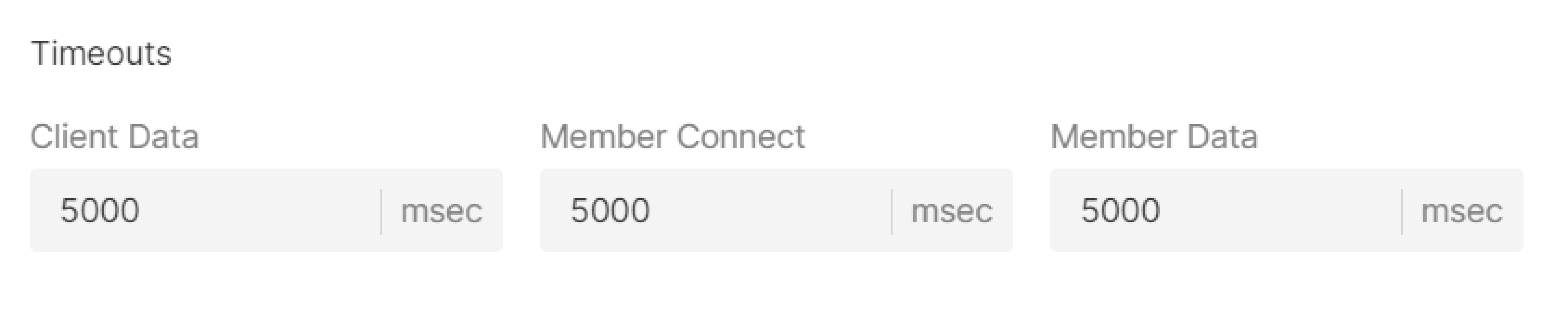
Step 7. Enter the name
Enter a name for the Load Balancer. This name will be displayed in the Gcore Customer Portal.
Step 8. (Optional) Enable logging
The Logging service will be activated to store your logs. To learn how it works and how to configure it, refer to the article about Logging.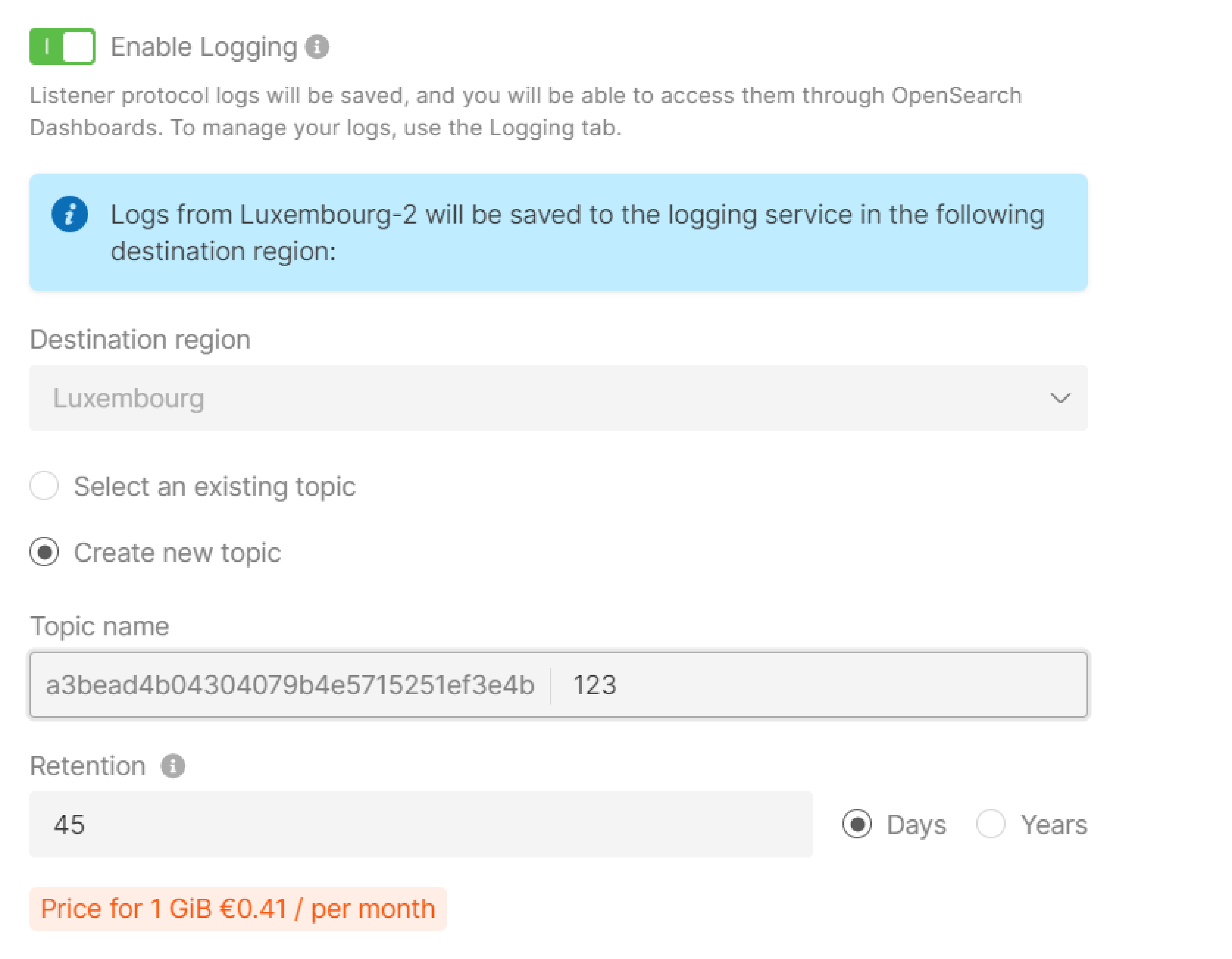
Step 9. (Optional) Add tags
Create tags for your load balancer by entering “Key” and “Value”.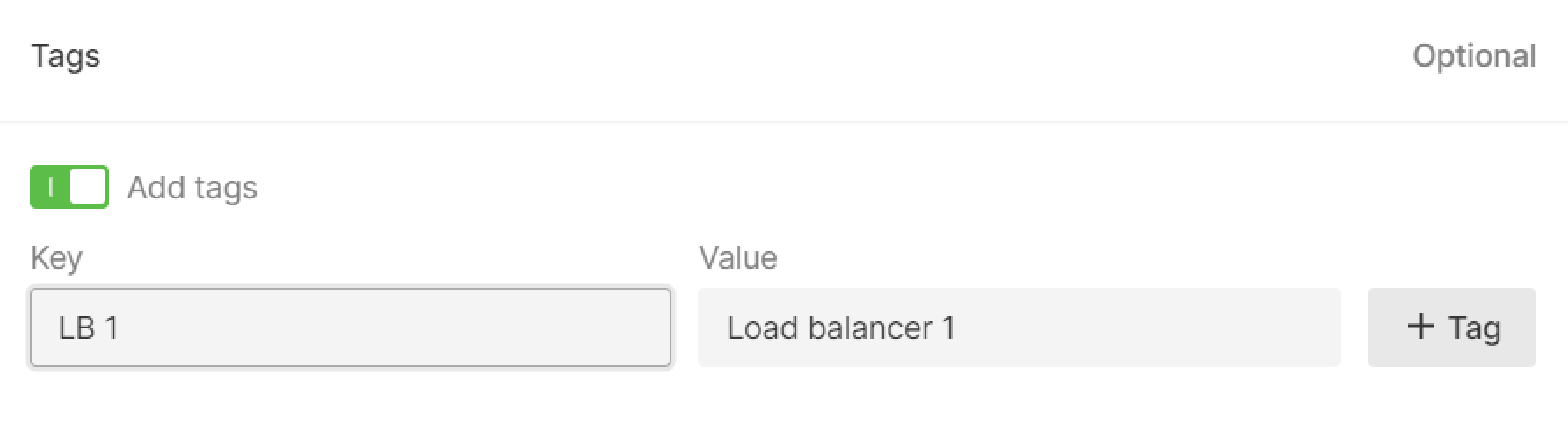
Step 10. Finalize creation
Check the settings and click Create Load Balancer on the right.Step 11. Configure firewall
Configure firewalls for Virtual Machines in the pool according to the separate guide. Make sure their ports are open for the Load Balancer traffic:- If a Load Balancer and Virtual Machines are in a public network, set a rule to receive and transmit traffic to the balancer’s IP address (specified in the menu) in firewalls settings of the VM.
- If a Load Balancer and Virtual Machines are in a private subnetwork, set a rule to receive and transmit traffic to the entire private subnetwork or to the balancer’s IP address (specified in the menu).
- If a Load Balancer is in a public network and Virtual Machine are in a private subnetwork, set a rule to receive and transmit traffic to the entire private subnetwork or to the balancer’s internal IP address (send a request to the technical support).